Monday, July 26, 2021

When off is not off, or "why is my amplifier pulling 30mA when it's off?"

 I have a little shed out the back with a 100W solar panel on it and a 13.8v battery. Right now it's just running a Raspberry Pi 2 powering an ADS-B decoder which works pretty well.

So then I added a little bluetooth audio amplifier from Fosi - https://fosiaudio.com/products/bluetooth-amplifier-bt10a . It's small, it's relatively efficient, and it's dumb as bricks to use.

But then I discovered something amusing.

It draws like 30mA even when turned off.

Here is the current meter when plugged into the battery side, but with it turned off.


.. and then I disconnect the power to it entirely, and  ...


High levels of what the heck.


So, I did what I always do when I find silly electronics questions - I disassembled it!

Here's the active power islands when it's turned off.


The MOSFET at the bottom is an IRF part that's .. always on. Then every other thing circled? That's also always on. That includes what look like opamp bits for the bass/treble filtering, and something op-amp-y feeding into the bluetooth audio offload PCB (that blue module.)

So what's the switch switching? Well, here's what's on the reverse of the PCB, showing the two power switch pins:


Note that one of those power pins is grounded. Yes, it's just some logic line feeding a silicon switch somewhere. And it's definitely not switching the IRF MOSFET at the beginning of the circuit - that'd be too easy.

Anyway. This amplifier will just pull ~ 350mW when turned off. I'm going to wire up a separate little switch and LED to feed power into the amplifier so I'm not discharging the battery for no reason.

But in any case, that's kinda hilarious.

Thursday, July 22, 2021

On calibrating up a ubitx, or "why the hell is this so complicated"

 I've built a few of ubitx/bitx40 radios over the last couple years. I built one of each for me, and a couple for other hams.

The biggest gotcha in this whole mess has been figuring out how to calibrate the thing. The ubitx has two oscillators to calibrate - the VFO and the BFO. The VFO is used for tuning, and the BFO is used for the third intermediate frequency (IF) to fall within the passband of the crystal filter.

However, exactly zero (0) of the PCBs I've received have been calibrated even remotely correctly, so I've had to go spend time figuring out how to do it myself. Unfortunately it's not been super easy - the instructions online make it sound way simpler than it really is, and unless you're super careful you're going to end up constantly being off frequency in SSB mode.

Ok, so here goes.

The ubitx radio is organised in a very specifically clever way for CW versus SSB, which makes calibration actually not TOO terrible. In SSB mode all three oscillators are used in a three stage IF design. In CW mode however, the transmit side doesn't bother with the SSB path at all - it directly unbalances the first IF mixer and transmits using the VFO oscillator directly on the transmit frequency.

So when calibrating the VFO, the reason it wants to calibrate it using transmit instead of receive is because it doesn't involve the BFO frequency /at all/. Instead, it's calibrating only the VFO frequency directly.

Now, what's it calibrating? Well, it's calibrating the crystal offset value, not a frequency offset in Hz. Ie, it's calibrating the offset between what you think 10MHz is when you program in 10MHz and what it's actually outputting. This affects all the clocks generated from the si5351 oscillator - not just the VFO!

This is important - when you calibrate the VFO, you're calibrating the whole frequency offset of the si5351, and that includes the BFO. Thus, if you calibrate the VFO, you will muck up your BFO offset.

When you do this stage, figure it out and write it down. I wish the offset was the whole 16 bit number so you could just dial THAT in, instead of how it's currently displayed (as a divided version of that, notionally ppm.)

I calibrate my VFO using a frequency counter and an RF tap. It's the only way to be sure. If you have a known-good receiver, you can tune it in SSB mode and do the math to figure out what the outputted tone will be at the given receive frequency. I've done this a couple times (before I bought a second hand frequency counter) using fldigi to display the audio spectrum, putting the radio into SSB mode and tuning to 9999.20 KHz. The 10MHz signal will show up as an 800Hz audio tone.

Anyway. Once you've done the VFO, it's time to calibrate the BFO. You have to NOT touch the VFO calibration at this point or it'll change your BFO calibration and you'll have to start again.

Ok, so the next oscillator is the USB/LSB frequency oscillator. The frequency is either ~57MHz or ~33MHz depending upon USB or LSB operation, so when the incoming signal mixes with this, the desired mixing product (either inverted or non inverted) shows up in the crystal filter passband. Now, in my v4 firmware I've made this also configurable, but by default it's a fixed value that they hope is in the passband of the crystal filter. I mention this only for completeness, you normally don't have to calibrate this.

The BFO calibration is more fiddly. This is the oscillator that when mixed with the output of the above stage brings the mixing product down to audio frequencies. (Ie, it's an SSB detector!)

When you start the calibration it'll reset to whatever the default is in the firmware, which is WAY off. When you start tuning in the BFO you'll hear the frequency spread of the background white noise shift as more of it comes into the passband, and .. then it'll disappear! And then as you keep tuning past the crystal filter frequency, it'll come back again! What's going on!

What's going on is that when you plot the frequency response of the crystal filter, it may not be exactly one big peak. A good example of it can be found here: https://ubitx.net/2018/04/14/ssb-crystal-filter-response/ .

Now, this is where things get a bit messy. When you change the BFO, it's not just changing the passband on the crystal oscillator. You need to make sure you're on the correct side of the filter so you're not getting an inverted copy of the mixing output.

The ubitx website suggests listening to an existing sideband transmission and figure out if you're on the right side by tuning the filter for maximum intelligibility. You can't use AM for this (eg WWV) because if you get the wrong side you'll hear a mirrored signal that sounds fine because it's AM, but you just won't be able to decode sideband.

What I do, since I have more than one good radio, is I hook up my ubitx to an antenna, my good radio to a dummy load, tune to them to the same frequency / sideband mode, set my transmit power to be like 5W on the good radio, and do a radio check. Yes, into my dummy load. The ubitx will definitely be able to hear it, and you can then set the BFO to maximise intelligibility and correct frequency centreing. You'll know for sure that you're on the right side of the crystal filter / mixing output because you'll definitely not hear yourself clearly otherwise.

After that? Well, I think we need a better way to characterise and calibrate both the USB/LSB frequencies rather than them being static as well as the BFO, and do them together. Ideally we'd be able to tweak both in order to definitely hit the right peak point of the crystal filter to minimise losses, but that will complicate the calibration quite a bit.

Anyway! Good luck calibrating your ubitx!

Monday, December 28, 2020

Repairing and bootstrapping an IBM PC/AT 5170, Part 3

So! In Parts 1 and 2 I covered getting this old thing cleaned up, getting it booting, hacking together a boot floppy disc and getting a working file transfer onto a work floppy disc.

Today I'm going to cover what it took to get it going off of a "hard disk", which in 2020 can look quite a bit different than 1990.

First up - what's the hard disk? Well, in the 90s we could still get plenty of MFM and early IDE hard disks to throw into systems like this. In 2020, well, we can get Very Large IDE disks from NOS (like multi hundred gigabyte parallel ATA interface devices), but BIOSes tend to not like them. The MFM disks are .. well, kinda dead. It's understandable - they didn't exactly build them for a 40 year shelf life.

The IBM PC, like most computers at the time, allow for peripherals to include software support in ROM for the hardware you're trying to use. For example, my PC/AT BIOS doesn't know anything about IDE hardware - it only knows about ye olde ST-412/ST-506 Winchester/MFM drive controllers. But contemporary IDE hardware would include the driver code for the BIOS in an on-board ROM, which the BIOS would enumerate and use. Other drive interconnects such as SCSI did the same thing.

By the time the 80386's were out, basic dumb IDE was pretty well supported in BIOSes as, well, IDE is really code for "let's expose some of the 16 bit ISA bus on a 40 pin ribbon cable to the drives". But, more about that later.

Luckily some electronics minded folk have gone and implemented alternatives that we can use. Notably:

  • There's now an open-source "Universe IDE BIOS" available for computers that don't have IDE support in their BIOS - notably PC/XT and PC/AT, and
  • There are plenty of projects out there which break out the IDE bus on an XT or AT ISA bus - I'm using XT-IDE.
Now, I bought a little XT-IDE + compact flash card board off of ebay. They're cheap, it comes with the universal IDE bios on a flash device, and ...

... well, I plugged it in and it didn't work. So, I wondered if I broke it. I bought a second one, as I don't have other ISA bus computers yet, and ...

IT didn't work. Ok, so I know that there's something up with my system, not these cards. I did the 90s thing of "remove all IO cards until it works" in case there was an IO port conflict and ...

.. wham! The ethernet card. Both wanted 0x300. I'd have to reflash the Universal IDE BIOS to get it to look at any other address, so off I went to get the Intel Etherexpress 8/16 card configuration utility.

Here's an inside shot of the PC/AT with the XT-IDE installed, and a big gaping hole where the Intel EtherExpress 8/16 NIC should be.


No wait. What I SHOULD do first is get the XT-IDE CF card booting and running.

Ok, so - first things first. I had to configure the BIOS drive as NONE, because the BIOS isn't servicing the drive - the IDE BIOS is. Unfortunately, the IDE BIOS is coming in AFTER the system BIOS disks, so I currently can't run MFM + IDE whilst booting from IDE. I'm sure I can figure out how at some point, but that point is not today.

Success! It boots!

To DOS 6.22!

And only the boot sector, and COMMAND.COM! Nooooo!

Ok so - I don't have a working 3.5" drive installed, I don't have DOS 6.22 media on 1.2MB, but I can copy my transfer program (DSZ) - and Alley Cat - onto the CF card. But - now I need the DOS 6.22 install media.

On the plus side - it's 2020 and this install media is everywhere. On the minus side - it's disk images that I can't easily use. On the double minus side - the common DOS raw disk read/write tool - RAWREAD/RAWRITE - don't know about 5.25" drives! Ugh!

However! Here's where a bit of hilarious old knowledge is helpful - although the normal DOS installers want to be run from floppy, there's a thing called the "DOS 6.22 Upgrade" - and this CAN be run from the hard disk. However! You need a blank floppy for it to write the "uninstallation" data to, so keep one of those handy.

I extracted the files from the disk images using MTOOLS - "MCOPY -i DISK.IMG ::*.* ." to get everything out  - used PKZIP and DSZ to get it over to the CF card, and then ran the upgrader.


Hello DOS 6.22 Upgrade Setup!


Ah yes! Here's the uninstall disc step! Which indeed I had on hand for this very moment!


I wonder if I should fill out the registration card for this install and send it to Microsoft.

Ok, so that's done and now I have a working full DOS 6.22 installation. Now I can do all the fun things like making a DOS boot disk and recovery things. (For reference - you do that using FORMAT /S A: to format a SYSTEM disk that you can boot from; then you add things to it using COPY.)

Finally, I made a boot disk with the Intel EtherExpress 8/16 config program on it, and reconfigured my NIC somewhere other than 0x300. Now, I had to open up the PC/AT, remove the XT-IDE and install the EtherExpress NIC to do this - so yes, I had to boot from floppy disc.


Once that was done, I added a bunch of basic things like Turbo C 2.0, Turbo Assembler and mTCP. Now, mTCP is a package that really needed to exist in the 90s. However, this and the RAM upgrade (which I don't think I've talked about yet!) will come in the next installment of "Adrian's remembering old knowledge from his teenage years!".

Thursday, December 17, 2020

Repairing and bootstrapping an IBM 5170 PC/AT, part 2

Ok, so now it runs. But, what did it take to get here?

First up - I'm chasing down a replacement fusable PROM and I'll likely have to build a programmer for it. The programmer will need to run a bit at a time, which is very different to what the EPROM programmers available today support. It works for now, but I don't like it.

I've uploaded a dump of the PROM here - https://erikarn.github.io/pcat/notes.html .

Here's how the repair looks so far:


Next - getting files onto the device. Now, remember the hard disk is unstable, but even given that it's only DOS 5.0 which didn't really ship with any useful file transfer stuff. Everyone expected you'd have floppies available. But, no, I don't have DOS available on floppy media! And, amusingly, I don't have a second 1.2MB drive installed anywhere to transfer files.

I have some USB 3.5" drives that work, and I have a 3.5" drive and Gotek drive to install in the PC/AT. However, until yesterday I didn't have a suitable floppy cable - the 3.5" drive and Gotek USB floppy thingy both use IDC pin connectors, and this PC/AT uses 34 pin edge connectors. So, whatever I had to do, I had to do with what I had.

There are a few options available:

  • You can write files in DOS COMMAND.COM shell using COPY CON <file> - it either has to be all ascii, or you use ALT-<3 numbers> to write ALT CODES. For MS-DOS, this would just input that value into the keyboard buffer. For more information, Wikipedia has a nice write-up here: https://en.wikipedia.org/wiki/Alt_code .
  • You can use an ASCII only assembly as above: a popular one was TCOM.COM, which I kept here: https://erikarn.github.io/pcat/tcomtxt.asm
  • If you have MODE.COM, you could try setting up the serial port (COM1, COM2, etc) to a useful baud rate, turn on flow control, etc - and then COPY COM1 <file>. I didn't try this because I couldn't figure out how to enable hardware flow control, but now that I have it all (mostly) working I may give it a go.
  • If you have QBASIC, you can write some QBASIC!
I tried TCOM.COM, both at 300 and 2400 baud. Both weren't reliable, and there's a reason it isn't - writing to the floppy is too slow! Far, far too slow! And, it wasn't enforcing hardware flow control, which was very problematic for reliable transfers.

So, I wrote some QBASIC. It's pretty easy to open a serial port and read/write to it, but it's not AS easy to have it work for binary file transfer. There are a few fun issues:

  • Remember, DOS (and Windows too, yay!) has a difference between files open for text reading/writing and files open for binary reading/writing.
  • QBASIC has sequential file access or random file access. For sequential, you use INPUT/PRINT, for random you use GET and PUT.
  • There's no byte type - you define it as a STRING type of a certain size.
  • This is an 8MHz 80286, and .. well, let's just say QBASIC isn't the fastest thing on the planet here.
I could do some basic IO fine, but I couldn't actually transfer and write out the file contents quickly and reliably. Even going from 1200 to 4800 and 9600 baud didn't increase the transfer rate! So even given an inner loop of reading/writing a single byte at a time with nothing else, it still can't keep up.

The other amusingly annoying thing is what to use on the remote side to send binary files. Now, you can use minicom and such on FreeBSD/Linux, but it doesn't have a "raw" transfer type - it has xmodem, ymodem, zmodem and ascii transfers. I wanted to transfer a ~ 50KB binary to let me do ZMODEM transfers, and .. well, this presents a bootstrapping problem.

After a LOT of trial and error, I ended up with the following:

  • I used tip on FreeBSD to talk to the serial port
  • I had to put "hf=true" into .tiprc to force hardware handshaking; it didn't seem to work when I set it after I started tip (~s to set a variable)
  • On the QBASIC side I had to open it up with hardware flow control to get reliable transfers;
  • And I had to 128 byte records - not 1 byte records - to get decent transfer performance!
  • On tip to send the file I would ask it to fork 'dd' to do the transfer (using ~C) and asking it to pad to the 128 byte boundary:
    • dd if=file bs=128 conv=sync
The binary I chose (DSZ.COM) didn't mind the extra padding, it wasn't checksumming itself.

Here's the hacky QBASIC program I hacked up to do the transfer:

OPEN "RB", #2, "MYFILE.TXT", 128

' Note: LEN = 128 is part of the OPEN line, not a separate line!
OPEN "COM1:9600,N,8,1,CD0,CS500,DS500,OP0,BIN,TB2048,RB32768" FOR RANDOM AS #1 LEN = 128

size# = 413 '413 * 128 byte transfer
DIM c AS STRING * 128 ' 128 byte record
FOR i = 1 TO size#
  GET #1, , c
  PUT #2, , c
NEXT i
CLOSE #2
CLOSE #1

Now, this is hackish, but specifically:
  • 9600 baud, 8N1, hardware flow control, 32K receive buffer.
  • 128 byte record size for both the file and UART transfers.
  • the DSZ.COM file size, padded to 128 bytes, was 413 blocks. So, 413 block transfers.
  • Don't forget to CLOSE the file once you've written, or DOS won't finalise the file and you'll end up with a 0 byte file.
This plus tip configured for 9600 and hardware flow control did the right thing. I then used DSZ to use ZMODEM to transfer a fresh copy of itself, and CAT.EXE (Alley Cat!)

Ok, so that bootstrapped enough of things to get a ZMODEM transfer binary onto a bootable floppy disc containing a half-baked DOS 5.0 installation. I can write software with QBASIC and I can transfer files on/off using ZMODEM.

Next up, getting XT-IDE going in this PC/AT and why it isn't ... well, complete.


Wednesday, December 16, 2020

Repairing and bootstrapping an IBM 5170 PC/AT, part 1

 I bought an IBM PC/AT 5170 a few years ago for a Hackerdojo project that didn't end up going anywhere.

So, I have a PC/AT with:

  • 8MHz 80286 (type 3 board)
  • 512K on board
  • 128K expansion board (with space for 512K extended RAM, 41256 RAM chip style)
  • ST4038 30MB MFM drive with some gunk on head or platter 3 (random head 3 read failures, sigh)
  • 1.2MB floppy drive
  • CGA card
  • Intel 8/16 ethernet card


Ok, so the bad disk was a pain in the ass. It's 2020, DOS on 1.2MB floppy disks isn't exactly the easiest thing to come across. But, it DOES occasionally boot.

But, first up - the BIOS battery replacement had leaked. Everywhere. So I replaced that, and had to type in a BASIC program into ROM BASIC to reprogram the BIOS NVRAM area with a default enough configuration to boot from floppy or hard disk.


Luckily someone had done that:


So, I got through that.

Then, I had to buy some double high density 5.25" discs. Ok, well, that took a bit, but they're still available as new old stock (noone's making floppy discs anymore, sigh.) I booted the hard disk and after enough attempts at it, it booted to the command prompt. At which point I promptly created a bootable system disc and copied as much of DOS 5.0 off of it as I could.


Then, since I am a child of the 80s and remember floppy discs, I promptly DISCCOPY'ed it to a second disc that I'm leaving as a backup.

And, for funsies, DOSSHELL.


Ok, so what's next?

I decided to buy an alternate BIOS - the Quadtel 286 image that's floating about - because quite frankly having to type in that BASIC program into ROM BASIC every time was a pain in the ass. So, in it went. Which was good, because...

Well, then it stopped working. It turns out that my clean-up of the battery leakage wasn't enough. The system booted with three short beeps and "0E" on the screen.

Now we get into deep, deep PC history.

Luckily, the Quadtel BIOS codes are available here:


.. but with the Intel BIOS, it didn't beep, it didn't do anything. Just a black screen.

What gives?

So, starting with PC/AT and clone machines, the BIOS would write status updates during boot to a fixed IO port. Then if you have a diagnostic card that monitors that IO port, you'd get updates on where the system go to during boot before it hit a problem. These are called POST (power on self test) codes.

Here's a write-up of it and some POST cards:


Luckily, the Quadtel BIOS just spat it out on the screen for me. Phew.

So! 0xE says the 8254 interval timer wasn't working. I looked on the board and ... voila! It definitely had a lot of rusty looking crap on it. U115, a 32 byte PROM used for some address line decoding also was unhappy.

Here's how it looked before I had cleaned it up - this is circa July:


I had cleaned all of this out and used some vinegar on a Q-tip to neutralise the leaked battery gunk, but I didn't get underneath the ICs.

So, out they both came. I cleaned up the board, repaired some track damage and whacked in sockets.

Then in went the chips - same issue. Then I was sad.

Then! Into the boxes of ICs I went - where I found an 8254-2 that was spare! I lifted it from a dead PC clone controller board a while ago. In IT went, and the PC/AT came alive again.

(At this point I'd like to note that I was super afraid that the motherboard was really dead, as repairing PC/AT motherboards is not something I really wanted to do. Well, it's done and it works.)

Rightio! So, the PC boots, CGA monitor and all, from floppy disc. Now comes the fun stuff - how do I bootstrap said PC/AT with software, given no software on physical media? Aha, that's in part 2.

Friday, July 24, 2020

RFI from crappy electronics, or "how's this sold in the US?"

I picked up a cheap charging cable for my Baofeng UV-9S. (https://www.amazon.com/gp/product/B07TSDSQ4Z/). It .. well, it works.

But it messes up operating my radios! I heard super strong interference on my HF receiver and my VHF receivers.

So, let's take a look. I setup a little antenna in my shack. The baofeng was about 6ft away.


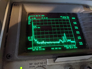
Here's DC to 120MHz. Those peaks to the right? Broadcast FM. The marker is at 28.5MHz.

Ok, let's plug in the baofeng and charger.

Ok, look at that noise. Ugh. That's unfun.

What about VHF? Let's look at that. 100-300MHz.

Ok, that's expected too. I think that's digital TV or something in there. Ok, now, let's plug in the charger, without it charging..


Whaaaaaaaaattttttt oh wait. Yeah, this is likely an unshielded buck converter and it's unloaded. Ok, let's load it up.


Whaaaaaa oh ok. Well that explains everything.

Let's pull it open:


Yup. A buck converter going from 5v to 9v; no shielding, no shielded power cable and no ground plane on the PCB. This is just amazing. The 3ft charge cable is basically an antenna. "Unintentional radiator" indeed.

So - even with a ferrite on the cable, it isn't quiet.


It's quiet at 28MHz now so I can operate on the 10m band with it charging, but this doesn't help at all at VHF.

Ew.


Wednesday, July 15, 2020

Fixing up ath_rate_sample to actually work well with 11n

Way back in 2011 when I was working on FreeBSD's Atheros 802.11n support I needed to go and teach some rate control code about 802.11n MCS rates. (As a side note, the other FreeBSD wifi hackers and I at the time taught wlan_amrr - the AMRR rate control in net80211 - about basic MCS support too, and fixing that will be the subject of a later post.)

The initial hacks I did to ath_rate_sample made it kind of do MCS rates OK, but it certainly wasn't great. To understand why then and what I've done now, it's best to go for a little trip down journey lane - the initial sample rate control algorithm by John Bicket. You can find a copy of the paper he wrote here - https://pdos.csail.mit.edu/papers/jbicket-ms.pdf .

Now, sample didn't try to optimise maximum throughput. Instead, it attempts to optimise for minimum airtime to get the job done, and also attempted to minimise the time spent sampling rates that had a low probability of working. Note this was all done circa 2005 - at the time the other popular rate control methods tried to maintain the highest PHY rate that met some basic success rate (eg packet loss, bit error rate, etc, etc.) The initial implementation in FreeBSD also included multiple packet size bins - 250 and 1600 bytes - to allow rate selection based on packet length.

However, it made some assumptions about rates that don't quite hold in the 802.11n MCS world. Notably, it didn't take the PHY bitrate into account when comparing rates. It mostly assumed that going up in rate code - except between CCK and OFDM rates - meant it was faster. Now, this is true for 11b, 11g and 11a rates - again except when you transition between 11b and 11g rates - but this definitely doesn't hold true in the 802.11n MCS rate world. Yes, between MCS0 to MCS7 the PHY bitrate goes up, but then MCS8 is MCS0 times two streams, and MCS16 is MCS0 times three streams.

So my 2011/2012 just did the minimum hacks to choose /some/ MCS rates. It didn't take the length of aggregates into account; it just used the length of the first packet in the aggregate. Very suboptimal, but it got MCS rates going.

Now fast-forward to 2020. This works fine if you're close to the other end, but it's very terrible if you're at the fringes of acceptable behaviour. My access points at home are not well located and thus I'm reproducing this behaviour very often - so I decided to fix it.

First up - packet length.  I had to do some work to figure out how much data was in the transmit queue for a given node and TID. (Think "QoS category.") The amount of data in the queue wasn't good enough - chances are we couldn't transmit all of it because of 802.11 state (block-ack window, management traffic, sleep state, etc.) So I needed a quick way to query the amount of traffic in the queue taking into account 802.11 state. That .. ended up being a walk of each packet in the software queue for that node/TID list until we hit our limit, but for now that'll do.

So then I can call ath_rate_lookup() to get a rate control schedule knowing how long a packet may be. But depending up on the rate it returns, the amount of data that may be transmitted could be less - there's a 4ms limit on 802.11n aggregates, so at lower MCS rates you end up only sending much smaller frames (like 3KB at the slowest rate.) So I needed a way to return how many bytes to form an aggregate for as well as the rate. That informed the A-MPDU formation routine how much data it could queue in the aggregate for the given rate.

I also stored that away to use when completing the transmit, just to line things up OK.

Ok, so now I'm able to make rate control decisions based on how much data needs to be sent. ath_rate_sample still only worked with 250 and 1600 byte packets. So, I extended that out to 65536 bytes in mostly-powers-of-two values.  This worked pretty well right out of the box, but the rate control process was still making pretty trash decisions.

The next bit is all "statistics". The decisions that ath_rate_sample makes depend upon accurate estimations of how long packet transmissions took. I found that a lot of the logic was drastically over-compensating for failures by accounting a LOT more time for failures at each attempted rate, rather than only accounting how much time failed at that rate. Here's two examples:
  • If a rate failed, then all the other rates would get failure accounted for the whole length of the transmission to that point. I changed it to only account for failures for that rate - so if three out of four rates failed, each failed rate would only get their individual time accounted to that rate, rather than everything.
  • Short (RTS/CTS) and long (no-ACK) retries were being accounted incorrectly. If 10 short retries occured, then the maximum failed transmission for that rate can't be 10 times the "it happened" long retry style packet accounting. It's a short retry; the only thing that could differ is the rate that RTS/CTS is being exchanged at. Penalising rates because of bursts of short failures was incorrect and I changed that accounting.
There are a few more, but you can look at the change log / change history for sys/dev/ath/ath_rate/sample/ to see.

By and large, I pretty accurately nailed making sure that failed transmit rates account for THEIR failures, not the failures of other rates in the schedule. It was super important for MCS rates because mis-accounting failures across the 24-odd rates you can choose in 3-stream transmit can have pretty disasterous effects on throughput - channel conditions change super frequently and you don't want to penalise things for far, far too long and it take a lot of subsequent successful samples just to try using that rate again.

So that was the statistics side done.

Next up - choices.

Choices was a bit less problematic to fix. My earlier hacks mostly just made it possible to choose MCS rates but it didn't really take into account their behaviour. When you're doing 11a/11g OFDM rates, you know that you go in lock-step from 6, 12, 18, 24, 36, 48, 54MB, and if a rate starts failing the higher rate will likely also fail. However, MCS rates are different - the difference between MCS0 (1/2 BPSK, 1 stream) and MCS8 (1/2 BPSK, 2 streams) is only a couple dB of extra required signal strength. So given a rate, you want to sample at MCS rates around it but also ACROSS streams. So I mostly had to make sure that if I was at say MCS3, I'd also test MCS2 and MCS4, but I'd also test MCS10/11/12 (the 2-stream versions of MCS2/3/4) and maybe MCS18/19/20 for 3-stream. I also shouldn't really bother testing too high up the MCS chain if I'm at a lower MCS rate - there's no guarantee that MCS7 is going to work (5/6 QAM64 - fast but needs a pretty clean channel) if I'm doing ok at MCS2. So, I just went to make sure that the sampling logic wouldn't try all the MCS rates when operating at a given MCS rate. It works pretty well - sampling will try a couple MCS rates either side to see if the average transmit time for that rate is higher or lower, and then it'll bump it up or down to minimise said average transmit time.

However, the one gotcha - packet loss and A-MPDU.

ath_rate_sample was based on single frames, not aggregates. So the concept of average transmit time assumed that the data either got there or it didn't. But, with 802.11n A-MPDU aggregation we can have the higher rates succeed at transmitting SOMETHING - meaning that the average transmit time and long retry failure counts look great - but most of the frames in the A-MPDU are dropped. That means low throughput and more actual airtime being used.

When I did this initial work in 2011/2012 I noted this, so I kept an EWMA of the packet loss both of single frames and aggregates. I wouldn't choose higher rates whose EWMA was outside of a couple percent of the current best rate. It didn't matter how good it looked at the long retry view - if only 5% of sub-frames were ACKed, I needed a quick way to dismiss that. The EWMA logic worked pretty well there and only needed a bit of tweaking.


A few things stand out after testing:

  • For shorter packets, it doesn't matter if it chooses the one, two or three stream rate; the bulk of the airtime is overhead and not data. Ie, the difference between MCS4, MCS12 and MCS20 is any extra training symbols for 2/3 stream rates and a few dB extra signal strength required. So, typically it will alternate between them as they all behave roughly the same.
  • For longer packets, the bulk of the airtime starts becoming data, so it begins to choose rates that are obviously providing lower airtime and higher packet success EWMA. MCS12 is the choice for up to 4096 byte aggregates; the higher rates start rapidly dropping off in EWMA. This could be due to a variety of things, but importantly it's optimising things pretty well.
There's a bunch of future work to tidy this all up some more but it can wait.